Thermocouples: Principle, Working, Materials and Applications
Ch. Devi Lal Government Polytechnic, Nathusari Chopta › Diploma in Engineering (Polytechnic) › Electrical Engineering › Semester 3
Thermocouples: Principle, Working, Materials and Applications
How does a power plant know how hot its boiler is? How does a gas geyser know that its flame has gone out? In both cases a small device called a thermocouple senses the temperature and gives an electrical signal. A thermocouple has no battery and no moving part. It is just two different metal wires joined together.
In this note you will learn the principle, the working, the materials and the applications of a thermocouple. This is an important topic, because a long answer with a diagram has been asked on it.
1. What Is a Thermocouple?
Definition: A thermocouple is a temperature-measuring device made of two wires of different metals joined together at two points (junctions). When the two junctions are at different temperatures, a small voltage (EMF) is produced.
Important point: A thermocouple is made of two different metals. A previous paper asked this as a True/False question, and the answer is True. If both wires were of the same metal, no EMF would be produced.
2. Principle: Seebeck Effect
Seebeck effect: When two different metals are joined to form a closed circuit and the two junctions are kept at different temperatures, an EMF is produced in the circuit and a current flows. This EMF is called the thermo-EMF (thermoelectric EMF).
The thermo-EMF depends on:
- the pair of metals used, and
- the difference of temperature between the two junctions.
The EMF is small (a few millivolts), but it is steady and can be measured.
Exam tip: A previous paper asked "Thermocouple works on the principle of ___" with options Joule effect, Peltier effect, Thomson effect and Seebeck effect. The answer is Seebeck effect.
| Effect | What happens |
|---|---|
| Seebeck effect | Temperature difference between two junctions of different metals produces an EMF (used in thermocouples) |
| Peltier effect | When current passes through a junction of two different metals, the junction becomes hot or cold (the opposite of Seebeck effect) |
| Thomson effect | Heat is given out or absorbed along a single conductor when current flows through it and its two ends are at different temperatures |
| Joule effect | Heat produced by a current flowing in a resistance (I2R heating) |
3. Construction and Working
Construction:
- Two wires of different metals, A and B, are welded together at one end. This is the hot junction (measuring junction). It is placed in the place whose temperature is to be measured, such as a furnace.
- The other ends are connected to a sensitive millivoltmeter. These ends are at a known, steady temperature and form the cold junction (reference junction).
- The millivoltmeter scale is marked directly in degrees Celsius.
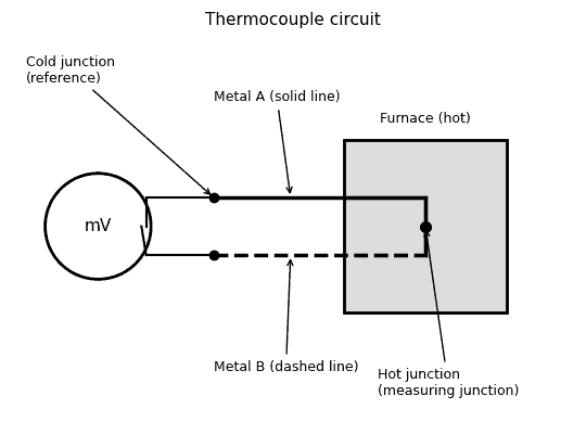 Fig. 1: Thermocouple circuit
Diagram in words: A solid line (metal A) and a dashed line (metal B) start at a dot inside a grey box marked "Furnace (hot)". This dot is the hot junction. The two lines run to the left to two more dots, the cold junction, where they connect to a circle marked "mV", the millivoltmeter.
Working:
- The hot junction is heated by the furnace, while the cold junction stays at room (or ice) temperature.
- Because of the temperature difference, a thermo-EMF is produced in the circuit (Seebeck effect).
- A small current flows through the millivoltmeter. The higher the furnace temperature, the greater the EMF and the reading.
- The reading of the meter shows the temperature.
Important point: The EMF depends on the difference between the two junction temperatures. So the cold junction temperature must be kept steady, or the meter must be corrected for it (cold junction compensation).
4. Materials Used in Thermocouples
| Thermocouple | Metals | Approximate range |
|---|---|---|
| Copper-constantan | Copper and constantan | about −200 to 350 °C |
| Iron-constantan | Iron and constantan | about 0 to 750 °C |
| Chromel-alumel | Chromel (nickel-chromium) and alumel (nickel-aluminium) | about −200 to 1250 °C |
| Platinum-rhodium | Platinum with platinum-rhodium alloy | up to about 1500 °C or more |
Note: The pairs and temperature ranges are standard textbook values. They are not given in the syllabus and differ a little between books.
Desirable properties of thermocouple materials:
- High thermo-EMF for a given temperature difference.
- EMF should rise steadily (almost in a straight line) with temperature.
- High melting point.
- Good resistance to oxidation and corrosion.
- Stable calibration over a long time.
- Good mechanical strength and ductility (drawn into wires).
- Low cost (for base-metal pairs).
5. Advantages and Limitations
| Advantages | Limitations |
|---|---|
| Wide temperature range, from very low to very high | Output is very small (millivolts) and needs a sensitive meter or amplifier |
| Simple, strong and cheap | Needs a steady cold junction or compensation |
| Quick response; measures temperature at a point | Accuracy is moderate (about a degree or more) |
| No external power supply is needed | EMF does not rise in an exactly straight line with temperature |
6. Applications of Thermocouples
- Measuring temperature of furnaces, kilns and ovens
- Measuring temperature of boilers, steam lines and turbines in power plants
- Temperature measurement in engines, exhaust gases and chemical plants
- Flame-failure safety in gas geysers, stoves and heaters (the thermocouple cuts off the gas when the flame goes out)
- Temperature protection and monitoring of electrical machines and transformers
- Thermocouple-type instruments for measuring high-frequency currents (current heats the hot junction)
Everyday Examples to Remember
- The small metal tip beside the flame of a gas geyser or heater: a thermocouple safety device.
- The thin probe pushed into an industrial furnace: a thermocouple.
MCQ and True/False Facts
- A thermocouple works on the Seebeck effect.
- A thermocouple is made of two different types of metal (True).
- Seebeck effect: temperature difference between junctions gives EMF. Peltier effect: current gives heating or cooling at a junction.
- The EMF depends on the metals and on the temperature difference of the two junctions.
Important Questions for Examinations
Short Answer Questions
- Discuss the working of a thermocouple and mention its important applications.
- What is the Seebeck effect? How does it differ from the Peltier and Thomson effects?
- Name the common thermocouple materials and their temperature ranges.
- Write the desirable properties of thermocouple materials, and the advantages and limitations of a thermocouple.
Long Answer Question
- Describe the thermocouple with a diagram and mention its important applications.
Quick Revision
- Thermocouple: two different metals, two junctions, EMF from temperature difference.
- Principle: Seebeck effect.
- Hot junction at the place to be measured; cold junction at a steady temperature; millivoltmeter in the circuit.
- Pairs: copper-constantan, iron-constantan, chromel-alumel, platinum-rhodium.
- Uses: furnaces, boilers, engines, flame safety, high-frequency current measurement.
Related Topics to Study Next
Before this note: Classification of Electrical Engineering Materials; High Resistivity Materials (constantan). Next: Soldering, Bimetals and Fuses.
Conclusion
A thermocouple turns heat into a small electrical signal by the Seebeck effect. It needs two different metals, a hot junction in the place to be measured, a steady cold junction and a millivoltmeter. It is simple, strong and works over a very wide range, which is why it is used from gas geysers to power plant boilers.
More notes in Electrical Engineering Materials
- Hard Magnetic Materials: Tungsten Steel, Chromium Steel, Cobalt Steel, Alnico and Hard Ferrites
- Materials Used in the Fabrication of Motors and Generators: Part-wise Materials and Reasons
- Materials Used in the Fabrication of a Transformer: Part-wise Materials and Reasons
- Soldering, Bimetals and Fuses: Solder Materials, Bimetallic Strip and Fuse Wire
- High Resistivity Materials: Constantan, Nichrome, Manganin, Tungsten, Carbon and Others
- Soft Magnetic Materials: Silicon Steel, C.R.G.O., Nickel-Iron, Mu Metal and Soft Ferrites
Comments (0)
Sign in or create an account to leave a comment.
No comments yet.