Cyclo-Converter Controlled AC Drives and Electric Braking
Ch. Devi Lal Government Polytechnic, Nathusari Chopta › Diploma in Engineering (Polytechnic) › Electrical Engineering › Semester 5
Cyclo-Converter Controlled AC Drives and Electric Braking
Some machines are very large and run very slowly, such as the ball mill of a cement plant, a mine hoist or the propeller of a ship. For these, a cyclo-converter can feed the motor directly with low-frequency AC. When the machine has to be stopped or slowed quickly, electric braking is used.
In this note you will learn how a cyclo-converter controlled AC drive works, its advantages and limitations, and the basic concept and types of electric braking of an AC drive. You should know the cyclo-converter and the AC drive control methods first (see Related Topics).
1. Cyclo-Converter Controlled AC Drive
Concept: A three-phase to three-phase cyclo-converter converts the fixed-frequency AC supply directly into a variable, lower-frequency AC supply, without any DC link. This supply is given to an AC motor (induction or synchronous motor). Since the speed of the motor is proportional to the frequency, the motor speed is controlled by changing the output frequency of the cyclo-converter (Fig. 1).
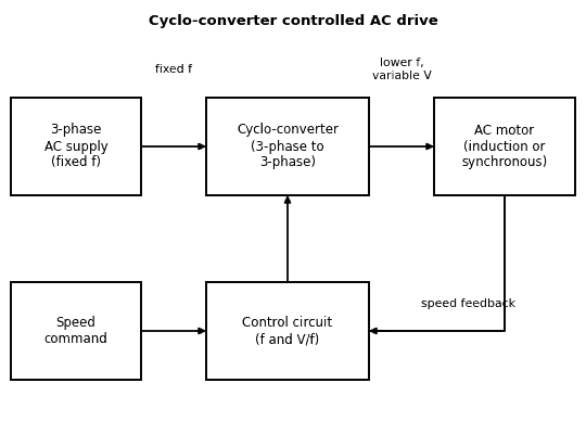 Fig. 1: Cyclo-converter controlled AC drive (block diagram)
Diagram in words: A three-phase AC supply of fixed frequency feeds a cyclo-converter (three-phase to three-phase). The cyclo-converter feeds an AC motor (induction or synchronous) with a lower frequency and variable voltage. A control circuit below the cyclo-converter sets the frequency and the V/f ratio. It receives a speed command and a speed feedback signal from the motor.
Working:
- The control circuit takes the speed command and the speed feedback from the motor.
- It sets the output frequency of the cyclo-converter. It also sets the output voltage in proportion to the frequency, so that V / f is constant (constant flux).
- The cyclo-converter makes the output wave from pieces of the three-phase supply, by firing its positive and negative groups of SCRs in the right order (Unit III). The SCRs are turned OFF naturally by the supply.
- The motor runs at a speed that depends on the output frequency. The output frequency is limited to about one-third to one-half of the supply frequency (textbook statement). For example, from a 50 Hz supply, the output can range from zero up to about 17 to 25 Hz, so the motor speed ranges from zero up to a fraction of its normal speed.
- Power can flow in both directions, so the motor can return energy to the supply during braking.
Applications:
- Large low-speed drives for cement mills, rolling mills, mine hoists (winders) and ship propulsion
- Gearless drives, where the motor is connected directly to the load without a gearbox
| Advantages | Limitations |
|---|---|
| Single-stage conversion with no DC link, so the efficiency is high | The output frequency is limited to a fraction of the supply frequency, so the speed range is limited |
| Natural commutation, so no commutation circuit is needed | A large number of SCRs and a complex firing circuit are needed, so the cost is high |
| Power can flow both ways (regenerative braking) | The supply power factor is poor, and the supply gets harmonics |
| Smooth torque at very low speeds | Not suitable for high-speed motors |
Exam tip: “Explain the concept of cyclo-converter controlled AC drive” has been asked as a 4-mark question.
2. Concept of Electric Braking
Definition: Braking means slowing down a rotating machine or bringing it to rest quickly, or holding a load at a constant speed against a force that tries to speed it up (for example, a lowering lift). In electric braking, the braking torque is produced by the motor itself, and a mechanical brake is not needed (or is needed only for holding at rest).
Why electric braking is used: It is smooth, quick, has no wear of brake shoes, and in regenerative braking the energy is returned to the supply.
Basic idea: In motoring, the motor takes electrical energy and gives mechanical energy. In braking, the motor works as a generator: it takes the mechanical (kinetic) energy of the load and either returns it to the supply or wastes it as heat in a resistor or in the motor.
Exam tip: “Explain the basic concept of electric braking for AC drive” has been asked as a 4-mark question.
3. Types of Electric Braking of an AC Drive
(a) Regenerative braking:
- If the motor is driven above its synchronous speed (for example, by an overhauling load) or if the supply frequency is reduced quickly in a variable frequency drive, the induction motor works as an induction generator.
- The power is returned to the supply through the converter (a converter that can pass power in both directions, such as a cyclo-converter or a bidirectional converter, is needed). If the converter cannot return power, the energy is wasted in a braking resistor.
- Advantage: energy saving and smooth braking. Limitation: it works only above a certain speed.
(b) Plugging (reverse current braking):
- Two of the three stator supply leads are interchanged. The direction of the rotating field reverses, and the torque now opposes the rotation of the rotor.
- The motor stops very quickly. But the current is very large, so resistances are connected in series, and the supply must be cut off at zero speed. Otherwise, the motor would start in the reverse direction.
- Limitation: much energy is lost as heat in the motor and the resistors.
(c) Dynamic braking (DC injection braking):
- The AC supply is disconnected from the stator, and a DC supply is connected to two of the stator terminals. This produces a stationary magnetic field.
- The rotor conductors cut this field, so the motor works as a generator and gives a braking torque. The energy is wasted as heat in the rotor circuit.
- Advantage: smooth and simple braking, and it can bring the motor to rest. Limitation: the energy is wasted, and the braking torque is small at low speed.
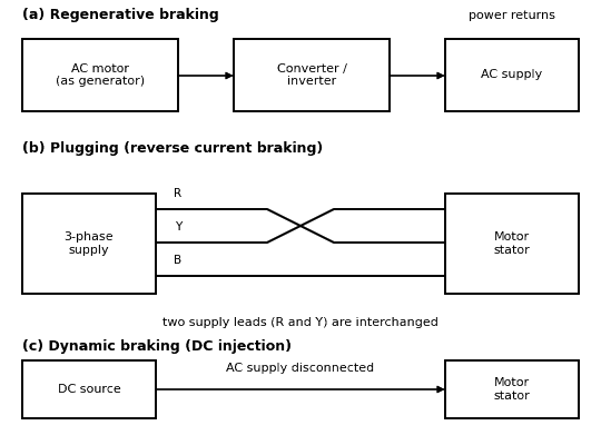 Fig. 2: Methods of electric braking of an AC motor (sketch)
Diagram in words: Three rows are shown. Row (a), regenerative braking: the motor acting as a generator sends power through a converter or inverter back to the AC supply. Row (b), plugging: three supply lines R, Y and B go to the motor stator, with two of the lines (R and Y) crossed. Row (c), dynamic braking: a DC source is connected to the stator while the AC supply is disconnected.
| Point | Regenerative braking | Plugging | Dynamic (DC injection) braking |
|---|---|---|---|
| Method | The motor works as a generator and returns power to the supply | Two supply leads are interchanged | DC is fed to the stator, with the AC disconnected |
| Energy | Returned to the supply | Wasted as heat | Wasted as heat |
| Stopping | Slow down only (above a certain speed) | Very quick; the supply must be cut at zero speed | Smooth stop to zero speed |
| Use | Variable frequency drives, cyclo-converter drives, trains | Machine tools, quick stopping | Fans, centrifuges, hoists |
Everyday Examples to Remember
- An electric train that slows down and sends energy back to the overhead line (regenerative braking).
- A lift going down with a heavy load: the motor acts as a generator and holds the speed (braking).
- A giant cement mill turning slowly with a gearless motor, powered by a cyclo-converter.
MCQ and True/False Facts
- A cyclo-converter converts AC to AC of a lower frequency without a DC link.
- In a cyclo-converter drive, the motor speed is controlled by the output frequency.
- In regenerative braking, the motor works as a generator and returns energy to the supply.
- In plugging, two supply leads of the motor are interchanged.
- In dynamic (DC injection) braking, a DC supply is connected to the stator.
Important Questions for Examinations
Short Answer Questions
- Explain the concept of a cyclo-converter controlled AC drive.
- State the advantages and limitations of a cyclo-converter controlled AC drive.
- Explain the basic concept of electric braking for an AC drive.
- Explain regenerative, plugging and dynamic (DC injection) braking of an AC drive.
Long Answer Questions
- Explain a cyclo-converter controlled AC drive and the types of electric braking used for AC drives.
Quick Revision
- Cyclo-converter drive: supply → cyclo-converter → AC motor; speed controlled by the output frequency; no DC link.
- Output frequency is limited to about one-third to one-half of the supply frequency.
- Uses: large low-speed drives (cement mills, rolling mills, mine hoists, ships).
- Braking: the motor works as a generator. Regenerative (energy returned), plugging (two leads interchanged), dynamic (DC injection).
Related Topics to Study Next
Cyclo-Converters (Unit III); AC Drives: Phase Control, Variable Frequency and Constant V/f Control; Electric Drives: Concept, Block Diagram and Advantages; Uninterrupted Power Supply (Unit V).
Conclusion
A cyclo-converter controlled AC drive feeds a motor directly with low-frequency AC, so large machines can run smoothly at low speed. Electric braking makes the motor work as a generator, and it can return the energy to the supply (regenerative braking) or waste it as heat (plugging and dynamic braking).
More notes in Industrial Electronics & Control of Drives
- AC Drives: Phase Control, Variable Frequency and Constant V/f Control
- DC Drives: Speed Control, Half-Wave, Full-Wave and Chopper Drives
- Electric Drives: Concept, Block Diagram and Advantages
- Thyristor (SCR) - Protection Methods and Technologies
- SCR : Construction, Working and V-I characterstics - Detailed
- Construction of SCR(Thyristor) | SCR Internal Arrangement
Comments (0)
Sign in or create an account to leave a comment.
No comments yet.