DC Drives: Speed Control, Half-Wave, Full-Wave and Chopper Drives
Ch. Devi Lal Government Polytechnic, Nathusari Chopta › Diploma in Engineering (Polytechnic) › Electrical Engineering › Semester 5
DC Drives: Speed Control, Half-Wave, Full-Wave and Chopper Drives
A DC motor is the oldest and the easiest motor to control for speed. In a DC drive, a thyristor converter gives a variable DC voltage to the motor, so the speed is changed smoothly without wasting power in a resistor.
In this note you will learn how the speed of a DC motor is controlled, and how half-wave, full-wave and chopper drives work. You should know the controlled rectifiers (Unit II) and choppers (Unit III) first (see Related Topics).
1. Speed Control of a DC Motor
For a DC motor, the back emf is Eb = Va − IaRa and Eb is proportional to φN. So the speed is:
N ∝ (Va − IaRa) / φ
Here Va is the armature voltage, Ia is the armature current, Ra is the armature resistance and φ is the flux per pole. This is a standard textbook relation. The speed can be changed by changing Va, φ or Ra.
| Method | What is changed | Speed obtained | Remark |
|---|---|---|---|
| Armature voltage control | Va (by a converter or chopper) | Below the normal (base) speed | Constant torque; smooth and efficient; used in thyristor drives |
| Field (flux) control | φ (by changing the field current) | Above the normal (base) speed | Constant power; limited speed range |
| Armature resistance control | Ra (resistor in series) | Below the normal speed | Wasteful; not used in thyristor drives |
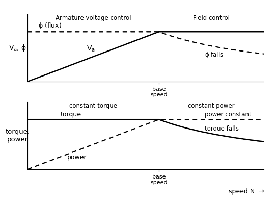 Fig. 1: Speed control regions of a DC motor (sketch)
Diagram in words: The upper graph has speed on the horizontal axis. The armature voltage Va rises in a straight line up to the base speed and then stays constant, while the flux φ stays constant up to the base speed and then falls. The lower graph shows the torque, which is constant up to the base speed and then falls, and the power, which rises up to the base speed and then stays constant. The left part is marked armature voltage control (constant torque) and the right part is marked field control (constant power).
The two methods are often used together. Below the base speed, the field is kept at its full value and Va is raised from zero to its rated value (constant torque). Above the base speed, Va is kept at its rated value and the field is weakened (constant power).
Exam tip: “Field control is used in DC motors to get …” and “which method is used to control the speed of a DC shunt motor above the normal speed?” have been asked as MCQs. The answers are: speed above the normal speed, and field (flux) control.
2. Half-Wave DC Drive
Circuit: A single SCR is connected in series with the armature of a DC motor and the AC supply. A freewheeling diode is connected across the armature. The field winding gets a separate, constant DC supply (Fig. 2).
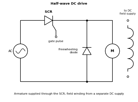 Fig. 2: Half-wave DC drive (circuit sketch)
Diagram in words: An AC source feeds an SCR in series with the armature of a DC motor (M). A freewheeling diode is connected across the armature, with its cathode on the SCR side. The field winding is drawn separately, with two open terminals marked to the DC field supply.
Working:
- In the positive half cycle, the SCR is triggered at the firing angle α. The armature gets the supply voltage and the motor speeds up.
- At the end of the half cycle, the SCR turns OFF. The armature current continues through the freewheeling diode, so the armature voltage does not become negative.
- In the negative half cycle, the SCR is OFF. The motor keeps running because of its inertia.
- The average armature voltage is (for continuous current, textbook relation):
Va = (Vm / 2π)(1 + cos α)
Speed control: If α is decreased, Va increases and the speed increases. If α is increased, Va decreases and the speed decreases.
Limitations: Only one half cycle is used, so the armature current has a large ripple and the torque pulsates. The supply current has a poor power factor. It is used only for small motors (fractional kW).
3. Full-Wave DC Drives
Full-wave drives use both half cycles of the supply. There are two types.
(a) Half-controlled (semi-converter) drive: The bridge has two SCRs and two diodes. The armature voltage is:
Va = (Vm / π)(1 + cos α)
The diodes give a natural freewheeling path, so the armature voltage never becomes negative. The drive works in one quadrant only: it can run the motor in one direction (motoring), but it cannot give regenerative braking.
(b) Fully controlled drive: The bridge has four SCRs (Fig. 3). For a highly inductive armature circuit, the armature voltage is:
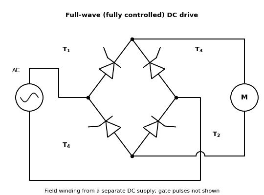 Fig. 3: Full-wave (fully controlled) DC drive (circuit sketch)
Diagram in words: Four SCRs T1 to T4 are connected as a bridge. The AC supply is connected to the left and right corners, and the armature of the DC motor (M) is connected between the top and bottom corners. The field winding gets a separate DC supply. In the half-controlled drive, T2 and T4 are replaced by diodes.
Va = (2Vm / π) cos α
- For α less than 90°, Va is positive and the motor works as a motor (rectifier mode).
- For α more than 90°, Va is negative and the converter works as an inverter. If the motor is rotating fast, it can return energy to the supply (regenerative braking).
So the fully controlled drive works in two quadrants. To reverse the motor, the field or the armature connections are reversed by a contactor. For full four-quadrant operation, a dual converter is used (Unit III). These are textbook relations for ideal devices.
Speed control: Changing α changes Va, and so the speed.
4. Chopper Drive
When the supply is DC (a battery or a DC line), a chopper is used to control the armature voltage (Fig. 4).
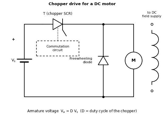 Fig. 4: Chopper drive for a DC motor (circuit sketch)
Diagram in words: A DC source Vs is connected through a chopper SCR T to the armature of a DC motor (M). A dashed box marked commutation circuit is shown below T. A freewheeling diode is connected across the armature. The field winding has its own supply (open terminals shown).
Working:
- When the chopper switch is ON for Ton, the full supply voltage Vs is applied to the armature.
- When it is OFF, the armature current continues through the freewheeling diode, and the armature voltage is zero.
- The average armature voltage is Va = D Vs, where D = Ton / T is the duty cycle. Increasing D increases the speed.
Features: A class A chopper gives motoring in one direction. Class C or class E choppers (Unit III) give regenerative braking and reversal. The efficiency is high and the speed control is smooth, and there is no ripple problem on the supply side if the supply is a battery.
Applications: Battery vehicles, forklifts, trolley buses, metro trains and electric locomotives.
5. Comparison of DC Drives
| Drive | Supply | Devices | Quadrants | Use |
|---|---|---|---|---|
| Half-wave | Single-phase AC | 1 SCR and 1 diode | One | Small motors |
| Half-controlled full-wave | Single-phase AC | 2 SCRs and 2 diodes | One | Medium motors, no braking |
| Fully controlled full-wave | AC (single or three-phase) | 4 SCRs (or 6) | Two | Larger motors with regenerative braking |
| Chopper | DC | SCR or switch, diode | One to four (class A to E) | Battery vehicles, traction |
Everyday Examples to Remember
- A battery-operated forklift or e-rickshaw uses a chopper drive.
- A metro train with regenerative braking returns energy to the supply while it slows down.
- A hand drill or mixer with a speed knob uses a small thyristor circuit for the motor.
MCQ and True/False Facts
- Field control of a DC motor gives speed above the normal speed.
- Flux control is used to get speed above normal speed in a DC shunt motor.
- Armature voltage control gives speed below the normal speed.
- A fully controlled converter uses thyristors only.
- In a chopper drive, Va = D Vs.
Important Questions for Examinations
Short Answer Questions
- Explain the methods of speed control of a DC motor. Which method is used to obtain speed above the normal speed?
- Explain the half-wave DC drive.
- Explain the full-wave (half-controlled and fully controlled) DC drives.
- Explain the chopper drive for a DC motor.
Long Answer Questions
- Explain the control of a DC motor using thyristor converters: half-wave, full-wave and chopper drives.
Quick Revision
- N ∝ (Va − IaRa) / φ. Armature voltage control: below base speed. Field control: above base speed.
- Half-wave: Va = (Vm/2π)(1 + cos α). Half-controlled: (Vm/π)(1 + cos α). Fully controlled: (2Vm/π) cos α.
- Fully controlled drive: α < 90° motoring, α > 90° regenerative braking.
- Chopper drive: Va = D Vs.
Related Topics to Study Next
Electric Drives: Concept, Block Diagram and Advantages; AC Drives; Controlled Rectifiers (Unit II); Choppers and Dual Converters (Unit III).
Conclusion
The speed of a DC motor is controlled by the armature voltage below the base speed and by the field flux above it. In a DC drive, a half-wave, full-wave or chopper circuit gives the variable armature voltage. The fully controlled and chopper drives can also give regenerative braking.
More notes in Industrial Electronics & Control of Drives
- Cyclo-Converter Controlled AC Drives and Electric Braking
- AC Drives: Phase Control, Variable Frequency and Constant V/f Control
- Electric Drives: Concept, Block Diagram and Advantages
- Thyristor (SCR) - Protection Methods and Technologies
- SCR : Construction, Working and V-I characterstics - Detailed
- Construction of SCR(Thyristor) | SCR Internal Arrangement
Comments (0)
Sign in or create an account to leave a comment.
No comments yet.